Solar bracket T-type clamp manufacturing method
Oct 30, 2018
With the development of industry, new energy is getting more and more attention, and the use of solar energy is more and more common. The existing solar panel installation usually adopts the installation of the rail at the bottom of the solar panel, and then the rail is installed to a required place by a plurality of bolts. This method has the disadvantages of large installation weight and poor safety factor, and the installation is time-consuming and labor-intensive for the work at height. In terms of it, there is a great inconvenience. Therefore, it is necessary to invent a Solar bracket T-type clamp to solve the above problems.
")
Technical realization elements:
The purpose of the present invention is to provide a Solar bracket T-type clamp to solve the problems raised in the above background art.
In order to achieve the above object, the present invention provides the following technical solution: a Solar bracket T-type clamp, comprising a first clamping plate and a second clamping plate, wherein one end of the first clamping plate and the second clamping plate are provided with a clamping portion, The other end of the first clamping plate is provided with a first folded portion, and the other end of the second clamping plate is provided with a second folded portion, the length of the first folded portion is smaller than the length of the second folded portion, The first hemming portion and the second hemming portion are both L-shaped, and the first hemming portion is caught at a corner of the second hemming portion, and the first hemming portion and the second hemming portion are a first through hole and a second through hole are respectively formed, a screw is disposed in the first through hole and the second through hole, and a screw is connected to the other end of the screw, and the second folded portion is further There are fixing holes.
Preferably, the inner side of the clamping portion is provided with a convex structure.
Preferably, the screw and the nut are provided with a gasket at a joint between the first through hole and the second through hole.
Preferably, the first hemming portion and the second hemming portion are provided with a water guiding trough, and the water guiding trough extends to the first through hole and the second through hole.
Preferably, the first clamping plate and the second clamping plate are an integrally cast structure.
Preferably, the fixing hole is located at a middle portion of the second hemming portion.
Compared with the prior art, the beneficial effects of the present invention are as follows: the Solar bracket T-type clamp is provided with a clamping portion at one end of the first clamping plate and the second clamping plate through the first clamping plate and the second clamping plate. The other end of the first clamping plate is provided with a first folded portion, and the other end of the second clamping plate is provided with a second folded portion, the length of the first folded portion is smaller than the length of the second folded portion, the first folded portion and The shape of the second hemming portion is L-shaped, and the first hemming portion is caught at the corner of the second hemming portion, thereby facilitating clamping of the first clamping plate and the second clamping plate, the first folding portion and the second folding portion a first through hole and a second through hole are respectively formed in the edge portion, a screw is arranged in the first through hole and the second through hole, and a nut is screwed on the other end of the screw to facilitate fixing the solar photovoltaic panel, and the second folding The side portion is further provided with a fixing hole for fixing on the house, and a water guiding groove is opened on the first folded portion and the second folded portion, and the water guiding groove extends to the first through hole and the second through hole, which is convenient for The water in the through hole is discharged, and the utility model has reasonable design, simple structure and convenient photovoltaic Fixed mount, do not compromise your roof houses, small buildings destroyed right now, and in advance to reserve a good location, easy to install solar PV mounting follow-up, it is worth promoting.
DRAWINGS
Figure 1 is a schematic view of the structure of the present invention;
Figure 2 is a side view of the present invention;
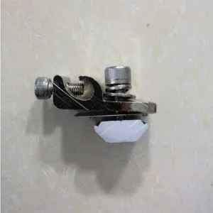
Figure 3 is a schematic perspective view of the utility model;
Figure 4 is a front elevational view of the present invention.
In the drawings: 1 first splint, 2 second splint, 3 clamping portion, 4 first hemming portion, 5 second hemming portion, 6 first through hole, 7 second through hole, 8 screw, 9 nut, 10 spacers, 11 fixing holes, 12 water guiding grooves, 13 raised structure.
Detailed ways
The technical solutions in the embodiments of the present invention will be clearly and completely described in conjunction with the accompanying drawings in the embodiments of the present invention. It is obvious that the described embodiments are only a part of the embodiments of the present invention, and not all of the embodiments. example. All other embodiments obtained by those skilled in the art based on the embodiments of the present invention without creative efforts are within the scope of the present invention.
In the description of the present invention, it should be noted that the terms 'center', 'upper', 'lower', 'left', 'right', 'vertical', 'horizontal', 'inside', 'outside' Or the indicated orientation or positional relationship is based on the orientation or positional relationship shown in the drawings, and is merely for the convenience of the description of the present invention and the simplified description, and does not indicate or imply that the device or component referred to has a specific orientation, The orientation configuration and operation are therefore not to be construed as limiting the invention; the terms 'first', 'second' and 'third' are used for descriptive purposes only and are not to be construed as indicating or implying relative importance; Unless specifically stated and limited, the terms 'mounted,' 'connected,' and 'connected' are used in a broad sense and may be, for example, a fixed connection, a detachable connection, or an integral connection; it may be a mechanical connection, It can also be an electrical connection; it can be directly connected, or it can be connected indirectly through an intermediate medium, which can be the internal connection of two components. The specific meanings of the above terms in the present invention can be understood by those skilled in the art in a specific case.
1-4, a Solar bracket T-type clamp includes a first clamping plate 1 and a second clamping plate 2, and one end of the first clamping plate 1 and the second clamping plate 2 is provided with a clamping portion 3, The other end of a splint 1 is provided with a first hemming portion 4, and the other end of the second cleat 2 is provided with a second hemming portion 5, the length of the first hemming portion 4 being smaller than the second hemming portion 5 The length of the first hem portion 4 and the second hem portion 5 are both L-shaped, and the first hem portion 4 is caught at the corner of the second hem portion 5, the first fold a first through hole 6 and a second through hole 7 are respectively formed in the edge portion 4 and the second flange portion 5, and the first through hole 6 and the second through hole 7 are internally provided with a screw 8 for the screw 8 The other end is threadedly connected with a nut 9, and the second flange portion 5 is further provided with a fixing hole 11.
Specifically, the inner side of the clamping portion 3 is provided with a convex structure 13 .
Specifically, a gasket 10 is disposed at a joint between the screw 8 and the nut 9 and the first through hole 6 and the second through hole 7.
Specifically, the first flange portion 4 and the second flange portion 5 are provided with a water guiding groove 12, and the water guiding groove 12 extends to the first through hole 6 and the second through hole 7.
Specifically, the first clamping plate 1 and the second clamping plate 2 are integrally cast structures.
Specifically, the fixing hole 11 is located at a middle portion of the second hem portion 5.
Working principle: the Solar bracket T-type clamp, in use, through the first clamping plate 1 and the second clamping plate 2, at one end of the first clamping plate 1 and the second clamping plate 2 is provided with a clamping portion 3, the first clamping plate 1 The other end of the second clamping plate 2 is provided with a second hemming portion 5, and the length of the first hemming portion 4 is smaller than the length of the second hemming portion 5, the first hemming portion The shape of the portion 4 and the second hem portion 5 are both L-shaped, and the first hem portion 4 is caught at the corner of the second hem portion 5 to facilitate the clamping of the first clamping plate 1 and the second clamping plate 2, a first through hole 6 and a second through hole 7 are respectively formed in a folded edge portion 4 and a second folded portion 5, and the first through hole 6 and the second through hole 7 are internally provided with a screw 8 and the screw 8 is further A nut 9 is screwed to one end for convenient fixing of the solar photovoltaic panel, and a fixing hole 11 is further formed on the second folded portion 5 for convenient fixing on the house, and is opened on the first folded portion 4 and the second folded portion 5 The water guiding groove 12 extends to the first through hole 6 and the second through hole 7 to facilitate the discharge of water in the through hole.
The utility model has reasonable design, simple structure and convenient photovoltaic function. Fixed mount, do not compromise your roof houses, small buildings destroyed right now, and in advance to reserve a good location, easy to install solar PV mounting follow-up, it is worth promoting.