


U-bolt Steel Solar Mounting Structure Panel Racking System
WANHOS U-Bolt Steel Ground Mount Solar Racking System is a project-engineered fixed-tilt support solution for commercial and utility-scale photovoltaic arrays.
The galvanized steel frame can be configured with driven piles, ground screws or engineered concrete foundations, while model-specific U-bolt assemblies connect selected rails, purlins and supporting members for efficient field installation.
Module orientation, tilt, table size, member sections, U-bolt specification and corrosion protection are customized to the approved project design. Final capacity must be verified against the governing code, site wind and snow actions, terrain, module loads, geotechnical conditions and complete foundation load path.
Description
Fixed-Tilt Solar Ground Mounting
U-Bolt Steel Ground Mount Solar Racking System
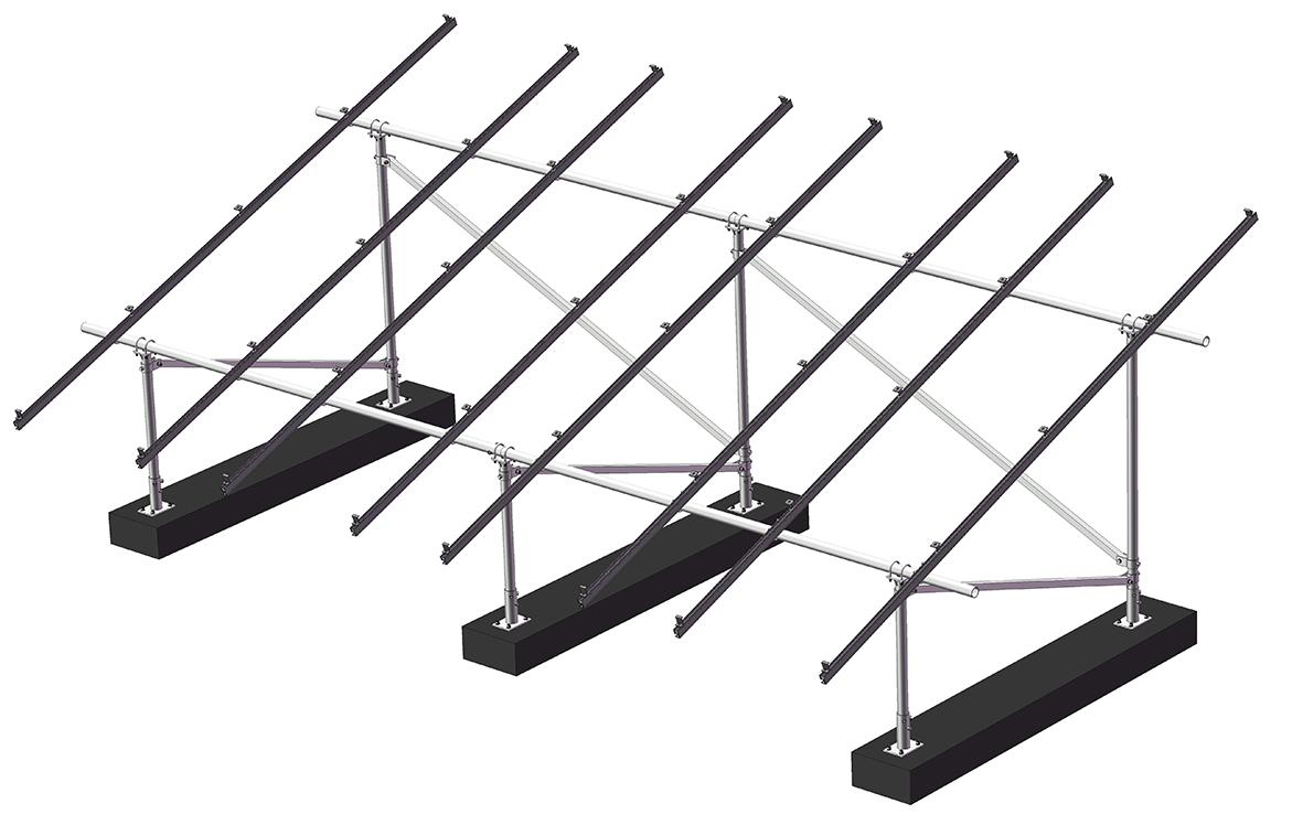
A project-engineered steel support structure for framed photovoltaic modules in open-field solar installations. U-bolt assemblies provide defined mechanical connections between selected rails, purlins or supporting members, while the complete structure transfers module dead load and environmental actions through the beams, posts and foundations into the ground.

Application
Open-Field PV Arrays
Connection
Model-Specific U-Bolts
Structure
Galvanized Steel Frame
Design Basis
Project Wind, Snow & Soil
Product Classification
This Is a Ground-Mount Structure, Not a Flat-Roof Ballast Bracket
The system shown is intended for open-field PV support. It uses foundations, posts, inclined beams and module-supporting rails or purlins. A roof ballast system has a different load path, aerodynamic behavior and waterproofing interface, so the two descriptions must not be mixed.
Product Overview
A Bolted Steel Structure Designed Around the Complete Project
WANHOS U-bolt steel solar racking is a fixed-tilt ground mounting solution for commercial and utility PV projects. Its bolted configuration can simplify field assembly and reduce site welding when components are manufactured, identified and packed according to the approved installation sequence.
The U-bolt is one connection within the system-not a universal indicator of structural capacity. Member sizes, U-bolt diameter and grade, tightening requirements, bracing, table length, foundation type and module clamps must all be verified in the project calculation and bill of materials.
System Benefits
Built for Repeatable Field Assembly
01
Bolted U-Bolt Connections
Approved U-bolts can connect matching structural members without relying on uncontrolled site welding. The exact geometry and torque remain connection-specific.
02
Factory-Prepared Components
Pre-cut members, prepared holes and labeled hardware can reduce measuring and fabrication work in the field when supplied to the approved drawings.
03
Foundation Flexibility
Driven piles, ground screws or engineered concrete foundations can be considered according to soil, loads, equipment access and local construction practice.
04
Project-Specific Layout
Tilt, module orientation, table size, ground clearance and row spacing can be configured around energy yield, terrain and structural requirements.
Connection Detail
What Must Be Defined for Every U-Bolt Assembly
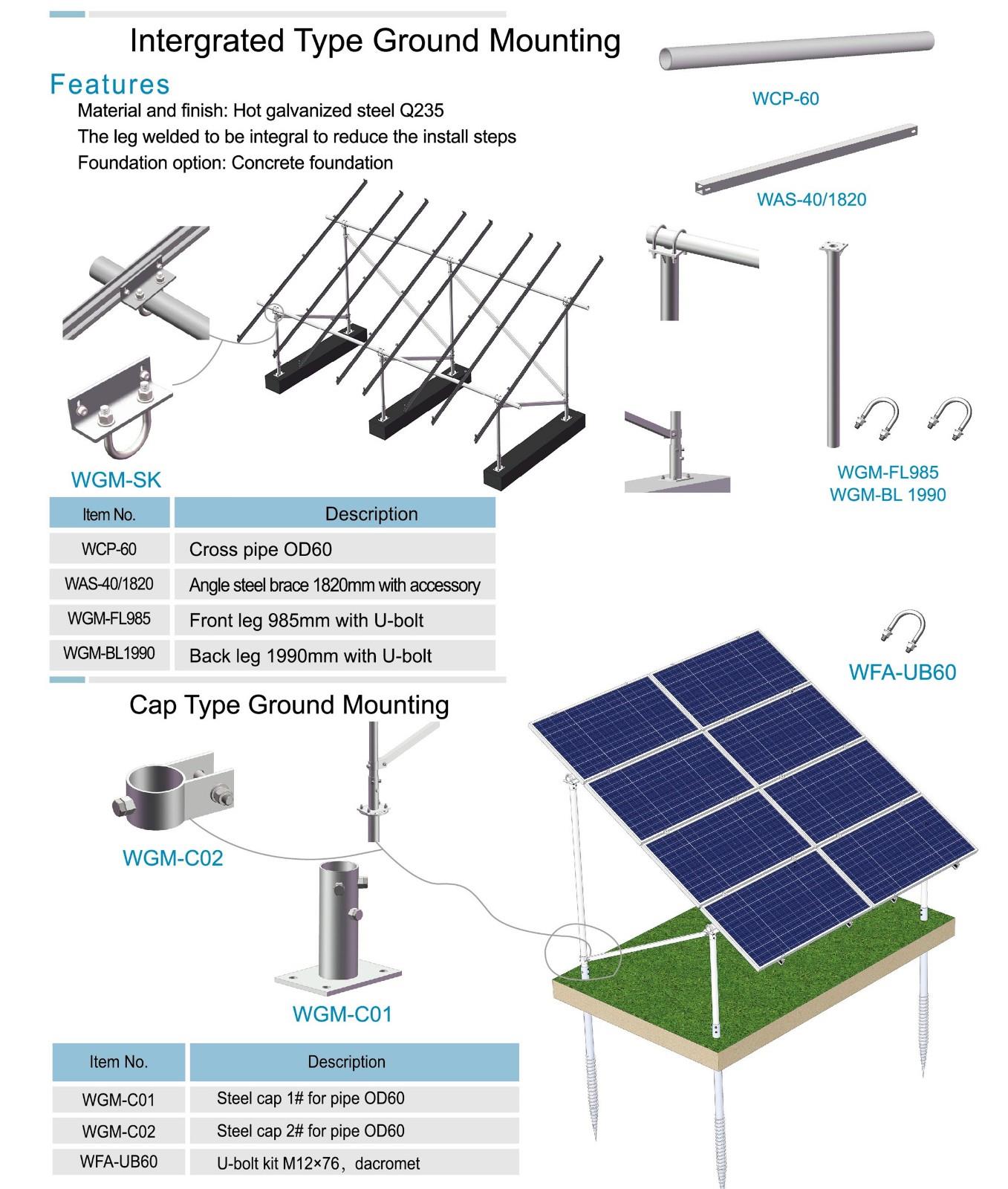
A U-bolt must match the member it wraps and the plate, bracket or rail it secures. Substituting a different diameter, material, thread or nut without engineering approval can change clamping force, bearing, slip and fatigue performance.
✓ Inside width and bend geometry matched to the supporting member
✓ Rod diameter, material grade and thread specification
✓ Saddle plate, washer, nut and locking arrangement
✓ Coating system and compatibility with connected materials
✓ Tightening sequence, installation torque and inspection method
✓ Capacity for shear, tension, bearing, slip and combined actions
Installation note: There is no safe universal torque for every U-bolt. Use only the value and tightening sequence stated in the approved connection drawing or installation manual, applied with a calibrated tool.


Structural Design Principle
Check the Complete Load Path, Not Only the Steel Member
Loads travel from the PV module through the module clamps, rails or purlins, U-bolt connections, inclined beams, bracing, posts and foundation before reaching the soil. Every interface must have adequate strength, stiffness and durability.
A statement such as "60 m/s wind resistance" is incomplete without the design code, wind region, terrain/exposure, topography, array geometry, tilt, height, safety factors and load combinations used to calculate structural actions.
System Components
A Complete Ground-Mount Assembly
Foundation
Driven steel pile, ground screw or reinforced concrete footing selected from geotechnical and structural design.
Posts and Supports
Front/rear or central support members transferring table reactions into the foundation.
Inclined Beams
Primary members defining the approved module tilt and supporting rails or purlins.
Rails or Purlins
Module-supporting members sized for span, deflection, clamp zones and environmental loads.
U-Bolt Assemblies
Connection-specific U-bolts, plates, washers and nuts installed to approved torque.
Module Clamps
Mid and end clamps matched to module frame height and manufacturer-approved clamp zones.
Bracing
Longitudinal or transverse bracing provided where required for stability and load distribution.
Bonding and Grounding
Approved electrical bonding components and grounding provisions according to the project electrical design.
Technical Data
Reference Specifications and Project Variables
System Type
Fixed-tilt U-bolt steel solar ground mounting system
Installation Site
Open field, subject to terrain, drainage, geotechnical and access review
Module Compatibility
Approved framed modules after dimensional, clamp-zone, load and grounding review
Module Orientation
Portrait or landscape according to the engineered layout
Reference Tilt Range
10–60° can be reviewed; final tilt follows energy, shading, structural and maintenance design
Primary Structure
Project-specified carbon-steel profiles with approved corrosion protection
Other Components
Aluminum rails/module clamps and stainless or coated-steel fasteners may be used according to the confirmed bill of materials
Surface Protection
Hot-dip galvanizing for fabricated steel and anodizing for aluminum where specified; coating requirements are project-specific
Foundation Options
Driven pile, ground screw or engineered concrete foundation
Wind and Snow Design
Calculated from the governing project code, site conditions, array geometry and load combinations; no universal rating
Standards
AS/NZS 1170, Eurocodes, ASCE 7 or other specified local standards, only where included in the approved design scope
Warranty
10 years subject to written terms, approved design, environment, storage, installation and maintenance
Design Service Life
Project-specific; must be supported by structural, corrosion and maintenance requirements rather than a generic material claim
Engineering Review
Design Checks That Define the Final Structure
Wind Actions
Regional wind climate, terrain/exposure, topography, array height, tilt, row geometry, local pressure zones and dynamic effects.
Snow and Ice
Ground snow, shape factors, sliding, accumulation, unbalanced or partial loading and clearance below the lower module edge.
Member Strength
Bending, shear, axial force, combined actions, local/global buckling, deflection and vibration of rails, beams, bracing and posts.
Connections
U-bolt tension, bearing, shear, slip, plate deformation, thread engagement, module clamp forces and connection interaction.
Foundation and Soil
Compression, uplift, lateral resistance, settlement, frost, scour, groundwater, slope stability and field load-test requirements.
Thermal and Corrosion
Table expansion, movement joints, coating environment, material compatibility, drainage, cut-edge repair and maintenance access.
Corrosion Protection
Specify the Coating, Environment and Repair Method
Hot-dip galvanizing can protect fabricated steel members, but the purchase specification should state the applicable standard, coating requirements and inspection method. Aluminum parts, stainless fasteners and galvanized steel must also be reviewed for material compatibility and water-trapping details.
Coastal salt, industrial pollutants, agricultural chemicals, persistent moisture and soil contact can increase corrosion demand. Design life depends on the actual exposure, coating system, component geometry, maintenance and permitted field repairs.
Avoid unapproved cutting or welding after coating. Where field modification is permitted, repair the affected area according to the project coating specification and document it during inspection.
Installation Workflow
A Controlled Sequence from Foundations to Modules
1. Survey and Set Out
Verify coordinates, boundaries, services, drainage, elevations and foundation positions against the approved layout.
2. Install Foundations
Control position, elevation, verticality, embedment and test requirements for piles, screws or concrete foundations.
3. Assemble Posts and Beams
Install labeled members in the specified orientation. Keep connections adjustable until the table geometry is verified.
4. Fit U-Bolts and Rails
Use the correct U-bolt, plate and hardware at each location. Tighten in sequence to the approved value.
5. Install and Clamp Modules
Maintain module gaps, clamp zones, overhangs and torque according to the module and racking instructions.
6. Inspect and Record
Check geometry, bolt marking, torque records, coating damage, bonding, drainage clearance and as-built deviations.
Information Required
What to Send for Design and Quotation
✓ Project location, coordinates and site elevation
✓ Governing structural code and design working life
✓ Wind, snow, seismic and temperature design inputs
✓ Terrain/exposure, topography and corrosion category
✓ Module brand, model, dimensions, weight and datasheet
✓ Portrait/landscape layout and modules per table
✓ Tilt, azimuth, ground clearance and row spacing
✓ Site plan, contours, slopes and drainage information
✓ Geotechnical report, groundwater and frost depth
✓ Preferred foundation and field-test requirements
✓ Bonding, cable management and maintenance clearances
✓ Quantity, schedule, packaging and destination port
Quality Documentation
What a Procurement Package Should Contain
✓ Approved general arrangement and connection drawings
✓ Structural calculation scope and design assumptions
✓ Final bill of materials and component identification
✓ Steel, aluminum and fastener material certificates
✓ Galvanizing/coating specification and inspection reports
✓ U-bolt and module clamp installation torque schedule
✓ Installation manual and construction tolerances
✓ Packing list, pallet marks and traceability plan
Frequently Asked Questions
U-Bolt Steel Solar Racking FAQ
What is a U-bolt solar mounting structure?
It is a solar support system in which approved U-bolt assemblies form selected mechanical connections between structural members. The complete system also includes rails, beams, posts, bracing, module clamps and foundations.
Is this a flat-roof ballast system?
No. This product is presented as an open-field fixed-tilt ground structure. Roof ballast systems require a different design for roof capacity, waterproofing, friction, ballast and aerodynamic loads.
Can one U-bolt fit every rail or beam?
No. Inside dimensions, rod diameter, bend shape, thread, plate and fasteners must match the connected members and approved structural connection.
What torque should be used on the U-bolts?
Use only the connection-specific torque stated in the approved drawing or installation manual. Torque depends on the U-bolt material, diameter, thread, coating, nut and required connection behavior.
Can it withstand 60 m/s wind?
That cannot be confirmed from wind speed alone. The project calculation must consider the governing code, exposure, topography, array height and geometry, tilt, pressure zones, safety factors and complete load path.
Is 1.4 kN/m² the maximum snow load?
It should not be treated as a universal limit. Design snow actions depend on the site and code, including accumulation, sliding, shape factors and partial or unbalanced loading.
How is the module tilt selected?
Tilt is selected from energy yield, latitude, row shading, land use, snow behavior, wind demand, ground clearance and maintenance. Changing tilt requires a new structural and layout review.
Which foundations can be used?
Driven piles, ground screws or concrete foundations may be considered. Selection depends on soil layers, groundwater, rocks, frost, loads, equipment access, tolerances and local construction practice.
Can the system accommodate uneven terrain?
Moderate elevation variation may be managed through foundation levels, post lengths or approved adjustment details. Steep or irregular sites require a topographic layout and may need shorter tables or stepped rows.
Does it fit every framed solar module?
Module dimensions, frame thickness, allowable clamp zones, loads, grounding method and warranty instructions must be checked. "Universal" compatibility should not be assumed.
Can bifacial modules be installed?
They can be reviewed, but rail position, rear shading, torque-tube or beam geometry, cable routing, ground clearance and electrical design must be coordinated with the module supplier.
How is corrosion protection specified?
Confirm the site corrosion category, steel and aluminum finishes, galvanizing/coating standards, fastener compatibility, cut-edge repair and expected maintenance. "Galvanized" alone is not a complete specification.
What information is required for a quotation?
Provide location, design code, environmental loads, module datasheet, array layout, tilt, clearance, topography, geotechnical report, foundation preference, coating requirements, quantity and delivery schedule.
For Project Review
Start with the Module Layout, Site Loads and Soil
Send the module datasheet, table arrangement, project location, design criteria, topographic and geotechnical information, foundation preference and quantity. WANHOS can then review the structural configuration, U-bolt connections, bill of materials, documentation and export supply requirements.
Hot Tags: u-bolt steel solar mounting structure panel racking system, suppliers China, manufacturers, factory, customized, buy, price, pricelist, quotation, free sample


