

Double Portrait Structure For Ground Mount Project
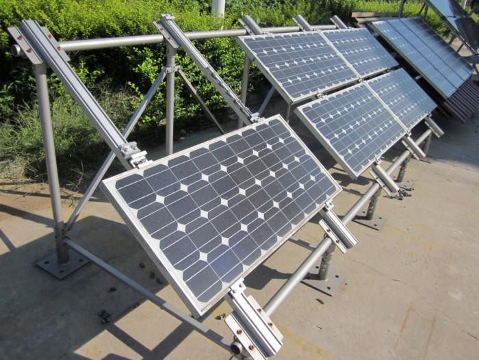
WANHOS Double Portrait Solar Ground Mounting Structure is a project-engineered fixed-tilt solution that supports two portrait-oriented PV modules from the lower edge to the upper edge of each table.
Designed for commercial and utility-scale open-field projects, the 2P structure can be configured with driven piles, ground screws or engineered concrete foundations and with aluminum or protected steel structural members.
Module dimensions, clamp zones, table length, tilt, row spacing, ground clearance, member sizes and corrosion protection are confirmed for each project. Final capacity must be verified against local wind, snow and seismic actions, terrain, module loads and geotechnical conditions.
Description
2P Fixed-Tilt Ground Mounting
Double Portrait Solar Ground Mounting Structure
A project-engineered fixed-tilt structure that arranges two portrait-oriented photovoltaic modules from the lower edge to the upper edge of each table. The 2P configuration is designed around the selected module, table length, tilt, row spacing, wind and snow actions, terrain and foundation conditions.

Module Layout
2 Modules in Portrait
Application
Open-Field Fixed Tilt
Foundation
Pile, Screw or Concrete
Design
Project-Specific Structure
Layout Clarification
What Does Double Portrait or 2P Mean?
Each module is installed in portrait orientation, with its long dimension running up the slope. Two modules are then positioned one above the other from the lower edge to the upper edge of the mounting table. This describes module layout only: it does not mean two foundations, two rows of tables or bifacial modules.
Product Overview
A Two-in-Portrait Table Designed as a Complete Load Path
WANHOS double portrait ground mounting uses posts, inclined beams, module-support rails or purlins, clamps, bracing and engineered foundations to support two portrait modules across the table slope. The configuration can suit commercial and utility PV projects where the energy layout and structural design favor a 2P table.
The final structure is not selected by the label "2P" alone. Current high-power modules vary significantly in length, width, frame thickness, weight and allowable clamping zones. Every quotation should therefore be based on the exact module datasheet and project conditions.
Why Choose 2P
Potential Project Advantages of Double Portrait Layout
01
Clear Portrait Module Layout
Two vertically oriented modules form the table slope, providing a consistent arrangement that can be repeated across long fixed-tilt rows.
02
Long-Side Clamp Compatibility
Many framed modules permit portrait mounting through clamps on their long frame sides, subject to the manufacturer's exact approved zones and load ratings.
03
Flexible Foundation Options
Driven piles, ground screws or engineered concrete foundations can be reviewed against the soil profile, structural reactions and construction method.
04
Factory-Prepared Assembly
Pre-cut members, prepared connections and labeled hardware can reduce field fabrication when the delivered kit follows the approved installation drawings.
Important Design Effect
A 2P Table Creates a Longer Slope Dimension
Because two module lengths extend from the low edge to the high edge, the table height difference, projected wind area, rear clearance, beam span and overturning reactions can differ from a 1P or landscape configuration.
The layout must therefore be checked for wind uplift and pressure, snow accumulation, member deflection, foundation reactions, installation access and module clamp loads. Double portrait is a design choice-not an automatic structural advantage.
2P Geometry
Dimensions That Control the Table Layout
Final table geometry should be issued on a project drawing. The following dimensions cannot be assumed from a catalog image.
Slope Length
Two module lengths plus the inter-module gap, end allowance and any approved overhang.
Table Length
Module widths, gaps, thermal breaks and end allowances multiplied across the selected modules per table.
Tilt Angle
Selected from energy, row shading, wind, snow, drainage, cleaning and structural requirements.
Lower-Edge Clearance
Set for vegetation, snow, drainage, soiling, maintenance and equipment access.
Upper-Edge Height
Derived from module dimensions, gaps, tilt and lower-edge clearance; checked for wind and access.
Row Pitch
Set from shading target, latitude, terrain, table height, maintenance routes and energy model.
Support Spacing
Calculated from rail, beam and post strength/deflection together with foundation capacity.

Module Compatibility
Start with the Exact Module Datasheet
"Framed module" does not mean universal compatibility. The module manufacturer defines allowable support or clamp zones, minimum clamp length, bolt or clamp torque, frame-side restrictions and mechanical load ratings. These requirements must be coordinated with the 2P rail arrangement.
Large-format and glass-glass modules may have different deflection, handling and clamping requirements. The structure must not shade the rear active area of bifacial modules or obstruct junction boxes, connectors and cable routes.
Portrait orientation is not the same as bifacial technology. Monofacial or bifacial modules may be evaluated for a 2P layout, but rear-side clearance and shading must be reviewed when bifacial energy gain is expected.

System Components
A Complete Double Portrait Support Assembly
Foundations
Driven piles, ground screws or engineered concrete foundations selected from soil and project loads.
Posts
Single-, twin- or front/rear-post arrangement according to the approved structural scheme.
Inclined Beams
Primary sloped members supporting the two-module portrait dimension.
Rails or Purlins
Module supports positioned within manufacturer-approved long-side clamp zones.
Mid and End Clamps
Matched to module frame geometry, clamp length, material and installation torque.
Bracing and Fasteners
Connection-specific braces, bolts, nuts and locking arrangements for table stability.
Bonding and Cable Support
Approved bonding paths and cable-management components coordinated with the electrical design.

Technical Data
Reference Specifications to Confirm
System Type
Fixed-tilt double portrait / two-in-portrait ground mounting structure
Installation Site
Open field, subject to topographic, drainage, geotechnical and access review
Module Arrangement
Two portrait modules from lower to upper edge; modules per table length are project-specific
Module Compatibility
Approved framed modules after dimensional, clamp-zone, load, grounding and warranty review
Tilt Angle
Project-specific according to energy, shading, wind, snow, drainage and maintenance design
Structural Materials
Aluminum and/or project-specified carbon-steel members with approved fasteners and coatings
Corrosion Protection
Anodizing, hot-dip galvanizing or other specified system based on material and site environment
Foundation Options
Driven pile, ground screw or engineered concrete footing
Wind, Snow and Seismic
Calculated using the specified project code, site conditions, table geometry and load combinations; no universal rating
Terrain Adaptation
Foundation levels, post lengths, table breaks and adjustment details by topographic design
Warranty
10 years subject to written terms, approved design, environment, storage, installation and maintenance
OEM & ODM
Available after engineering, tooling, testing, quantity and commercial review
Engineering note: Do not publish one wind speed or snow-load value as a universal 2P system capacity. Structural actions depend on the design code, wind climate, terrain/exposure, topography, tilt, table height and length, array spacing, snow behavior and safety factors.
Structural Design
Checks Required for the Complete 2P Table
Wind Actions
Pressure and uplift from wind climate, exposure, topography, tilt, table height, module gaps, row interference and local zones.
Snow Behavior
Uniform, unbalanced, partial, sliding and accumulated snow together with lower-edge clearance and drainage.
Modules and Clamps
Frame capacity, approved long-side clamp zones, clamp length, torque, overhang and module deflection.
Members and Connections
Strength, buckling, serviceability, stability, thermal movement and bolted connection behavior.
Foundation Reactions
Compression, uplift, lateral load and moment transferred into the pile, screw or concrete footing.
Terrain and Drainage
Slope, erosion, scour, groundwater, flood level, frost, vegetation and construction tolerances.

2P vs. Landscape
Choose the Layout by Project Performance, Not Habit
Double Portrait / 2P
Two module lengths form the slope direction.
Often uses long-side clamp zones.
May create a taller high edge at the same tilt and clearance.
Member spans, wind effects and access must be checked for the exact module.
Landscape Alternatives
Module width or multiple landscape modules form the slope direction.
Rail direction and clamp positions may differ.
Can produce a different table height and row pitch.
Compatibility must still follow the module manufacturer's mounting instructions.
Neither layout is always better. Compare energy yield, land use, steel quantity, foundation count, electrical routing, installation time and lifetime maintenance for the project.
Installation Workflow
From Set-Out to Module Inspection
1. Survey the Site
Confirm coordinates, contours, drainage, underground services, access and foundation positions.
2. Install Foundations
Control position, elevation, verticality, embedment and any required field testing.
3. Assemble the Frame
Fit posts, beams and bracing in the labeled sequence; verify tilt, diagonals and table alignment.
4. Position Module Rails
Set supports within the module's approved portrait clamp zones and tighten structural connections as specified.
5. Install Two Portrait Rows
Maintain the module gap, alignment, clamp engagement, torque and junction-box orientation required by the module supplier.
6. Complete QA Records
Inspect torque marks, coating damage, bonding, cable clearance, table geometry and as-built deviations.
Information Required
What to Send for a Reliable 2P Proposal
✓ Module manufacturer, model and full datasheet
✓ Module dimensions, frame thickness, weight and clamp zones
✓ Modules per table length and total installed quantity
✓ Project location, coordinates and site elevation
✓ Governing code and design working life
✓ Wind, snow, seismic and temperature inputs
✓ Tilt, azimuth, lower-edge clearance and row pitch
✓ Topographic survey, slopes and drainage information
✓ Geotechnical report, groundwater and frost depth
✓ Preferred foundation and field-test requirements
✓ Corrosion category and coating requirements
✓ Delivery schedule, packing and destination port
Quality Documentation
Documents to Confirm Before Production
✓ Approved 2P general arrangement and table dimensions
✓ Structural calculation scope and design assumptions
✓ Foundation reactions and acceptance requirements
✓ Final bill of materials and connection drawings
✓ Material and coating certificates
✓ Fastener and module clamp torque schedule
✓ Installation manual and construction tolerances
✓ Packing list, pallet marks and traceability plan

Frequently Asked Questions
Double Portrait Ground Mount FAQ
What does 2P mean in solar mounting?
It means two modules in portrait orientation across the table slope. Each module's long dimension runs from the lower side toward the upper side of the structure.
Does double portrait mean bifacial modules?
No. Double portrait describes the physical layout. Monofacial or bifacial modules may be evaluated separately, subject to mounting, shading and electrical requirements.
Does 2P require two rows of foundations?
Not necessarily. The structure may use a single-post, twin-post or front/rear-post scheme. Foundation arrangement follows structural reactions, member spans and geotechnical conditions.
Is 2P better than landscape mounting?
Neither layout is universally better. Compare module compatibility, steel and foundation quantities, row spacing, energy yield, site geometry, wiring, installation and structural performance.
Can the structure fit every framed module?
No. Module length, width, frame thickness, weight, clamp zones, mechanical load ratings and warranty instructions must be checked before the rails and clamps are finalized.
Where are portrait modules clamped?
They are commonly clamped on the long sides of the frame, but only within the exact zones approved by the module manufacturer. Clamp length, engagement and torque must also comply.
How are tilt and row spacing selected?
They are coordinated through energy modeling, latitude, shading targets, table height, terrain, wind and snow design, drainage, land use and maintenance access.
Does a taller 2P table receive more wind load?
Table height and slope dimension affect aerodynamic behavior, but wind forces also depend on exposure, topography, tilt, row arrangement and code coefficients. A project calculation is required.
How is lower-edge clearance determined?
Consider snow depth and sliding, vegetation, drainage, soiling, flood level, ground variation, cleaning equipment and safe maintenance access.
Which foundation is suitable for a 2P structure?
Driven piles, ground screws and concrete foundations can all be considered. Selection depends on soil, groundwater, rocks, frost, compression/uplift/lateral reactions, equipment and local practice.
Can the system follow sloping or uneven land?
Moderate variation may be handled by foundation elevations, post lengths, approved adjustments and table breaks. A topographic model is required for steep or irregular terrain.
Can bifacial modules be used in 2P?
Yes, after confirming module approval, rear structural shading, ground clearance, albedo assumptions, junction boxes, cable routing and electrical design.
What is required for an accurate quotation?
Send the module datasheet, modules per table, project location, design code, wind/snow/seismic data, tilt, clearance, topography, geotechnical report, foundation preference, coating and quantity.
For Project Review
Confirm the Module Before Designing the 2P Table
Provide the exact module datasheet, table length, tilt, ground clearance, project location, design criteria, topography, geotechnical information, foundation preference and quantity. WANHOS can then review the 2P layout, structural configuration, bill of materials, documentation and export supply plan.
Hot Tags: double portrait structure for ground mount project, suppliers China, manufacturers, factory, customized, buy, price, pricelist, quotation, free sample


